Controlled-Access Human Data - Policy and Requests
A. Read and complete the Data Use Certificate Agreement (DUC)
B. Complete the online Data Access Request (DAR) form
C. Select the Requested Datasets
D. Print, Gather Signatures and Submit the DUC and DAR forms
E. Receive notification and further instructions
F. Create and upload your encryption keys
G. Renew Access or Submit Closeout
Defining Surface Models for the Surface Mesh Viewer (3D models)
These instructions are for adding 3D models to the FaceBase site (see this information about our Surface Mesh Viewer). We assume you have uploaded ‘meshes’ to the site per the upload instructions. The instructions here assume you are logged in to the FaceBase site. If you need assistance, please don’t hesitate to contact FaceBase at: help@facebase.org.
Known Limitations
At this time, we know of the following limitations:
- Mesh file names must not include the ‘
;’ character, and it is probably best to avoid any “special characters” in mesh file names until further notice.
Create meshes and landmarks for upload
Avizo 9.5 software is able to generate meshes and landmarks that are commensurate with each other and will display accurately in the mesh viewer.
- Open the microCT scan (Nifti or DICOM) in Avizo and create a 3D Isosurface view.
- From the Isosurface view, create an extracted surface file.
- Choose surface view for the extracted surface. Click on surface view.
- Expand Buffer in the Properties Windows.
- Select Draw under Buffer to isolate the bone of interest in the 3D surface view. Important note: one must create a new extracted surface from the bone of interest again at this stage.
- Export the newly extracted surface as Wavefront (.obj).
- From the extracted surface file (step 2), repeat isolating other bones of interest (step 5).
- To add a landmark, open Slice from the root file (in step 1).
- In the Properties Windows, expand Plane Definition and select Show Dragger from Option.
- Drag the center of the planes (red dot) to the landmark of interest. XYZ coordinates (which appear as Plane Point under Plane Definition) will change accordingly.
- Record the XYZ coordinates.
- Repeat steps 10-11 for other landmarks.
Create the model record
Now you will define the surface model in your FaceBase Dataset:
- In FaceBase, log in and go to your Dataset page.
- Scroll down the page to the 3D Surface Models section.
- Click the Add records button to the right of the section heading.
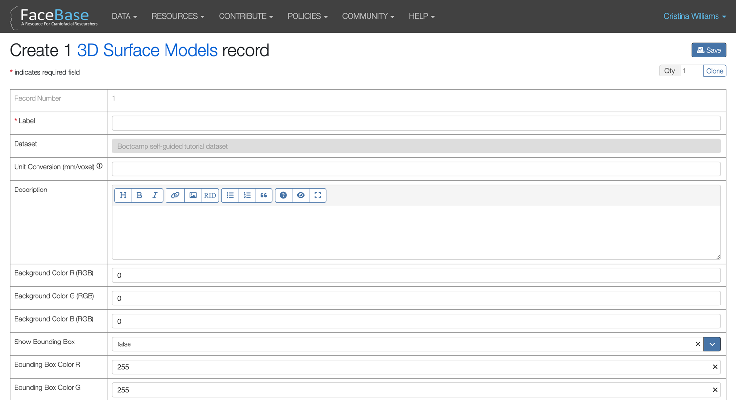
- Fill in the form:
- You must enter a ‘Label’ (i.e., name) for the model.
- We recommend entering a short description.
- You can define a background color (using the fields titled Background Color R (RGB), etc) in RGB color space using values from 0 to 255.
- You can always come back and edit these values.
- Click Save. Stay on this “3D Surface Model” page to add meshes (see next section).
Add meshes to your model
- Go to your 3D Surface Model page. If you just followed the instructions above, you will be on the right page. If not, go to your Dataset, scroll down to the 3D Surface Models section and click the Explore button and then click the View icon for the model.
- Scroll down to the Mesh Model Data section.
- Click the Add records button to the right of the section heading.
- Fill in the form:
- You must pick the ‘Mesh’. When you ‘Pick a value’ you will get a listing of the known mesh files in the catalog. You can search for your mesh based on its file name or dataset accession number.
- You can customize the color (using the fields Color R, etc) in RGB color space.
- You can customize the opacity. Note: there are some flaws with opacity rendering and you should report problems to us if you encounter them.
- Click Save.
Add landmark points to your meshes
- Go to your Mesh Data element that you want to add the landmark points to. (You can go to your mesh data element by clicking the View icon in the Mesh Data section - available on the Dataset and Experiment page.)
- In the the Landmark section, click the Add records button.
- In the Landmark Create Record page enter:
- A Label for the landmark point. This will be the label displayed for the point in the mesh viewer.
- The Point X, Point Y and Point Z coordinates of the landmark point. These are represented as float values and you can enter as many decimal places as required by your model. These values don’t have any units and should be in the same unit conversion factor as your mesh data.
- Enter a Radius value for the size of the sphere representing the landmark point in the mesh viewer. The default value of 0.1 is typically fine but you can adjust it depending on your mesh values.
- Enter the Color R, Color G and Color B values to adjust the color of the landmark point in the mesh viewer. The default values are (255,0,0) which will produce a red point.
- Optionally, you can also enter an Anatomy value associate to the landmark point.
- If you only need to add a single point to your mesh, you can click the Save button in the top-right corner and your point will be added to your mesh. This landmark is shown in the mesh display if a user clicks the Show Landmarks button in the top menu of the mesh viewer.
- If you want to add additional landmark points, from the Landmark record, click the Copy button in the top-right corner to add a point with all values replicated from the original point. If you want to add more than one landmark, use the Clone field (under the Save button) to replicate more records. Edit only the fields that differentiate each point from the original one, e.g., Label and X, Y and Z coordinates. You can repeat this process to add as many new points as needed. When done editing all the new points, click the Save button. (Even though you can add up to 200 points at a time this way, we recommend that you repeat this procedure at about 10 or 15 at a time)
Review your new surface model
To review your entry, you will need to go back to the Dataset page. You may need to refresh the page for the changes to take effect.